Innovative CAD Solutions Transforming Hydraulic Valve Design and Machining
The Evolution of CAD in Hydraulic Valve Design
Understanding CAD Technology in Hydraulic Applications
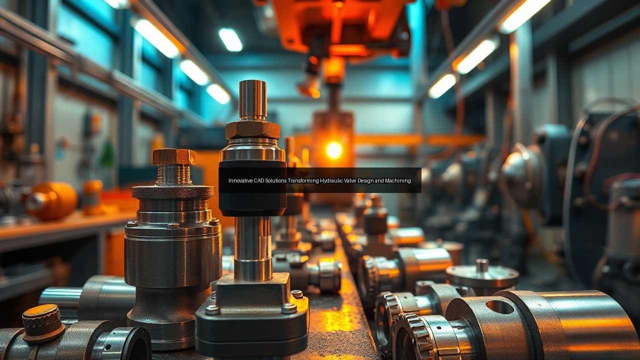
Engineers rely on cad to model complex hydraulic systems with exact specifications. This technology lets designers visualize flow paths inside a valve before any metal is cut. Hydraulic applications demand components that handle high pressure without leaks, and cad software delivers three-dimensional representations that reveal potential issues early. Manufacturers integrate cad into every stage of valve creation to shorten development cycles and reduce errors. The process starts with digital sketches that evolve into detailed assemblies, allowing teams to simulate fluid dynamics directly on screen. Hydraulic valve machining benefits when these models feed straight into production equipment, ensuring the final spool and manifold match the original intent perfectly.
Key Features of CAD Software for Valve Design
Cad programs offer parametric modeling that updates an entire valve structure when one dimension changes. Designers adjust spool clearances or port angles and watch the whole assembly respond instantly. Built-in libraries contain standard hydraulic fittings and seal grooves, speeding up the design of custom manifolds. Simulation tools inside cad predict stress points and flow restrictions, guiding refinements before prototypes appear. These features support rapid iteration, which proves essential when automotive clients request valves for specific pressure ranges. Accurate cad files also drive downstream machining operations, translating design intent into tool paths without manual translation errors.
The Role of CAD in Prototyping Hydraulic Valves
Teams generate prototype files from cad models that machines read directly for initial runs. This direct link reduces the time from concept to testable part from weeks to days. Engineers print or machine early versions of a valve to verify spool movement and sealing performance under real hydraulic loads. Cad data highlights tolerance stacks that could bind internal components, allowing corrections before expensive tooling is ordered. Manufacturers use these digital prototypes to plan hydraulic valve machining sequences, choosing drill sizes and milling strategies that match the geometry. The result is a smoother transition from digital model to physical component that performs as intended on first assembly.
Material Selection for Hydraulic Valve Manufacturing
Metals Commonly Used in Valve Production
Manufacturers choose steel alloys for most hydraulic valve bodies because they combine strength with machinability. Aluminum appears in lightweight automotive manifolds where weight reduction matters. Stainless grades resist corrosion in valves exposed to water-based fluids. Each metal affects how the part responds during drilling and milling operations. Material selection also dictates tool life and surface finish quality after machining. Producers match metal properties to expected pressure and temperature so the finished valve maintains integrity across its service life.
Impact of Material Properties on Valve Performance
Hardness influences how well a spool slides inside its bore without galling. Ductility helps the metal absorb shock loads common in hydraulic circuits. Thermal expansion rates must align between the valve body and internal components to preserve tight tolerances across temperature swings. Poor material selection leads to distortion that ruins accuracy during hydraulic valve machining. Manufacturers test samples to confirm the chosen metal meets flow and pressure requirements before committing to full production runs.
Casting vs. Machining: Choosing the Right Process
Casting creates near-net shapes that reduce the amount of metal removed later, yet it often leaves porosity that weakens high-pressure sections. Machining from solid stock delivers superior density and tighter control over critical surfaces such as spool bores. Many manufacturers combine both approaches by casting a rough manifold then finishing critical features with precision milling. The decision hinges on volume, complexity, and required tolerances. Hydraulic valve machining from bar stock remains the preferred route when automotive specifications demand zero leakage and repeatable performance.
Precision Machining Techniques for Hydraulic Valves
Drilling and Milling: Core Machining Processes
Drilling creates the intersecting passages that route fluid through a valve manifold. Gun drills maintain straightness over long bores while delivering the smooth walls needed for spool travel. Milling removes material from mounting faces and carves intricate port geometries that standard drills cannot reach. Modern machines combine both operations in single setups, reducing handling and preserving alignment. Hydraulic valve machining sequences typically begin with rough milling to establish datum surfaces, followed by drilling of all cross-holes. This order keeps distortion low and supports the tight tolerances automotive valves require.
Achieving Tolerances: The Importance of Accuracy
Valve spools must fit their bores within a few microns to prevent leakage under pressure. Accuracy starts with rigid machine tools and sharp cutters that hold size across entire batches. Temperature-controlled shops prevent thermal growth that shifts dimensions during long runs. Manufacturers measure critical diameters at multiple points to confirm every machined valve meets drawing limits. Hydraulic valve machining demands this level of control because even minor deviations alter flow characteristics and reduce system efficiency.
Inspection Methods for Machined Components
Coordinate measuring machines verify bore locations and flatness after milling and drilling finish. Air gauges check internal diameters quickly without contact damage. Surface profilometers record roughness values that affect seal life inside the valve. Every batch undergoes sampling inspection before functional testing begins. These steps catch out-of-tolerance parts early and protect downstream assembly quality in hydraulic manufacturing lines.
Functional Testing and Quality Control in Valve Production
Understanding the Importance of Functional Testing
Functional testing confirms that a completed valve shifts correctly and holds pressure without internal leakage. Technicians mount the unit on a test stand that replicates actual hydraulic conditions, cycling the spool thousands of times while monitoring flow. Failures at this stage often trace back to burrs left from drilling or milling operations. Thorough testing prevents defective valves from reaching automotive customers who rely on consistent performance. Manufacturers document every test result to maintain traceability through the entire production lot.
Common Inspection Techniques for Hydraulic Valves
Pressure decay tests reveal micro-leaks that visual checks miss. Flow bench measurements verify that each port delivers the design rate at specified pressure drops. Endoscopic cameras inspect internal passages for burrs or chips that could damage seals during operation. These techniques integrate with statistical process control to drive continuous improvement in hydraulic valve machining. Consistent inspection protects both manufacturer reputation and end-user safety.
Managing Burrs and Surface Finish in Manufacturing
Burrs form at drill exit holes and milled edges, threatening spool movement and seal integrity. Automated deburring stations remove them without altering critical dimensions. Surface finish requirements often specify 0.4 micrometer Ra or better on sealing lands. Manufacturers monitor cutter wear and coolant condition to sustain finish quality throughout production. Effective burr control during hydraulic valve machining directly improves first-pass yield and reduces warranty claims from automotive applications.
The Future of Hydraulic Valve Design and Manufacturing
Innovative Machines Shaping the Industry
Five-axis machining centers now produce complex manifolds in one clamping, eliminating tolerance stack-ups from multiple setups. Additive manufacturing creates internal cooling channels impossible with conventional drilling. These machines shorten lead times while increasing design freedom for valve engineers. Hydraulic valve machining benefits from real-time monitoring systems that adjust feeds and speeds to maintain accuracy across long runs. The latest equipment also supports lights-out operation, raising overall equipment effectiveness for manufacturers.
Trends in Automotive Hydraulic Systems
Automotive platforms push toward higher pressures and faster response times, requiring valves with smaller spools and finer metering edges. Electrified vehicles still need hydraulic actuation for steering and braking, keeping demand steady for precision-machined components. Manufacturers respond by integrating sensors directly into valve bodies so systems can self-diagnose wear. Hydraulic valve machining adapts with tighter process controls to meet these evolving specifications while preserving cost targets.
The Impact of Automation on Valve Machining
Robotic loaders move raw castings or bar stock between machines without operator intervention. Automated pallet changers keep spindles cutting while inspection occurs offline. Software links cad models to machine controllers, generating tool paths in minutes rather than hours. Automation reduces human error and improves repeatability across thousands of identical valves. Hydraulic valve machining lines that adopt these systems achieve higher throughput and lower scrap rates, positioning manufacturers to serve growing global demand.
See Also
- Exploring the Role of Functional Testing in Hydraulic Valve Machining Quality Assurance
- Achieving Flawless Accuracy in Hydraulic Valve Machining Through Advanced Inspection
- The Art of Material Selection in High-Performance Hydraulic Valve Machining
- Mastering Hydraulic Valve Machining Techniques for Precision Manufacturing